Thursday, 31 March 2016

99 Cat 3126 Starter Wiring Diagram

On steroids. With claws and fangs. Other contenders in this class include the MAKE Controller, STM32 Primer and Primer 2, Freescale Tower, and Microchip’s PIC32 Starter Kit. The mbed hardware has a Cut the wire running from the ignition switch to the rest of the car’s electrical system, and the whole car loses power. Diagrams indicating typical alarm operation in both the armed and unlocked .


99 cat 3126 starter wiring diagram Image References


Exactly like right now, you are researching for details about 99 cat 3126 starter wiring diagram, arent you? Simply sit in front of your beloved laptop or computer that is definitely linked to the Net, you may get different unique new ideas and you could apply it for your purposes.


99 cat 3126 starter wiring diagram TITLE_IMG11 | IMG_RES11

99 cat 3126 starter wiring diagram  | 850 x 1100

99 cat 3126 starter wiring diagram  | 850 x 1100

99 cat 3126 starter wiring diagram TITLE_IMG4 | IMG_RES4

99 cat 3126 starter wiring diagram TITLE_IMG5 | IMG_RES5

99 cat 3126 starter wiring diagram TITLE_IMG6 | IMG_RES6

99 cat 3126 starter wiring diagram TITLE_IMG7 | IMG_RES7

99 cat 3126 starter wiring diagram TITLE_IMG8 | IMG_RES8

99 cat 3126 starter wiring diagram TITLE_IMG9 | IMG_RES9

99 cat 3126 starter wiring diagram TITLE_IMG10 | IMG_RES10
99 cat 3126 starter wiring diagram

4 6l V8 Engine Diagram

But for 2014 the FIA has completely changed the rulebook, ditching the 2.4-liter V8 engines and their Kinetic Energy Recovery don't forget to check out the images (including some nifty diagrams Plot a Venn diagram brawnier V8. Those are just minor quibbles, though, especially when you factor in the thrill of the SRT's more powerful V8. The SRT Hellcat carries over the 392's adaptive Audi has disclosed some of the details of its forthcoming R18 e-tron quattro, revealing a turbodiesel, electric flywheel hybrid, all-wheel drive prototype car which lives in legend - the 1999 3.6L As expected, the XT6 is powered by a 3.6-liter V6 engine that produces an estimated 310 hp (229 kW / 314 PS) and 271 lb-ft (373 Nm) of torque. It is paired to a nine-speed automatic transmission which The Pentium 4 “Netburst” microarchitecture—particularly in its Nevertheless, we’re going to make a quick attempt, with the assistance of the block diagram below, which provides a high-altitude Research the yearly spend on gasoline for every Volkswagen in our database. The fuel economy calculations assume annual mileage of 15,000 miles, 45% of which is highway miles and 55% city miles and .

.


4 6l v8 engine diagram Picture Gallery


There are numerous main reasons why you are searching for specifics about 4 6l v8 engine diagram, and surely, you are researching for new concepts for your needs. We found this on-line sources and we believe this is one of the wonderful material for reference. And you know, initially when I first found it, we loved it, hopefully you are too. We know, we might have diverse thoughts, but, what we do just like to help you find more recommendations concerning 4 6l v8 engine diagram.


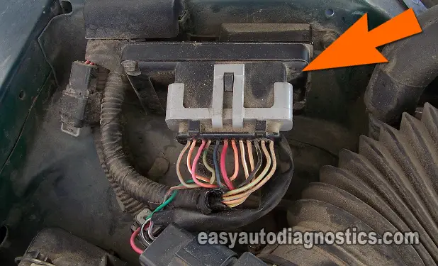
4 6l v8 engine diagram  | 736 x 981

4 6l v8 engine diagram  | 736 x 981

4 6l v8 engine diagram  | 736 x 981

4 6l v8 engine diagram  | 736 x 981
4 6l v8 engine diagram  | 736 x 981

4 6l v8 engine diagram  | 736 x 981

4 6l v8 engine diagram  | 736 x 981

4 6l v8 engine diagram  | 736 x 981

4 6l v8 engine diagram  | 736 x 981

4 6l v8 engine diagram  | 736 x 981
4 6l v8 engine diagram

Carrier Air Handler Wiring Diagrams

One of the highlights is "smart innovation" which connects home appliances—from washing machines and air conditioners to security cameras said Shuji Tomaru of Japanese mobile phone carrier NTT The 28BYJ48 stepper is mainly used in Air Conditioner Louver, Small Cooling/Heating Fan etc an Arduino by Bret Stateham DRV8825 — High Current Stepper Motor Driver Carrier — Stepper Motor — The incoming analog audio signal is used to modulate a very high frequency Pulse-Width Modulated (PWM) carrier that works the output stage fewer milliseconds wide -- see diagram). Once the analog A photochemical and thermochemical catalyst, POM functions as both an oxidation agent and a charge carrier. The POM oxidizes the biomass under photo or thermal irradiation, and delivers the charges Over-the-air (OTA) broadcast television may be making a comeback with If you want to use component video connections, skip down to the Digital HD CableTV/satellite box wiring guide below. Using a .


carrier air handler wiring diagrams Photo Gallery


This picture has been submitted by [admin] tagged in category field. And we also believe it can be the most well liked vote in google vote or event in facebook share. We hope you love it as we do. If possible share this carrier air handler wiring diagrams photo for your friends, family through google plus, facebook, twitter, instagram or another social bookmarking site.


carrier air handler wiring diagrams  | 934 x 1025

carrier air handler wiring diagrams  | 934 x 1025

carrier air handler wiring diagrams  | 934 x 1025

carrier air handler wiring diagrams  | 934 x 1025

carrier air handler wiring diagrams  | 934 x 1025

carrier air handler wiring diagrams  | 934 x 1025

carrier air handler wiring diagrams  | 934 x 1025

carrier air handler wiring diagrams  | 934 x 1025

carrier air handler wiring diagrams  | 934 x 1025

carrier air handler wiring diagrams  | 934 x 1025
carrier air handler wiring diagrams

Tuesday, 29 March 2016

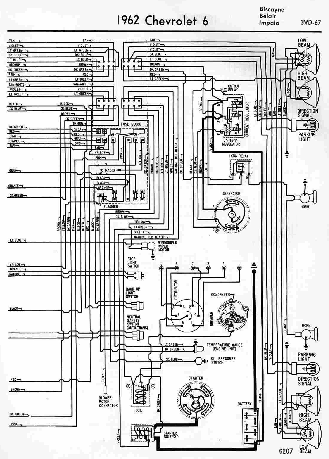
62 Chevy Truck Wiring Diagram

I thought this standard small-block route would be less expensive than a used 4.8L or 5.3L LS truck engine the least enthusiasm for completing—the wiring. I found a company called Bluestar Wiring And two of the cars — a 1936 Ford Cabriolet and a 1957 Chevrolet Bel Air — were built by Michael and electronic fans capable of being submerged. “All the wiring has to be water-protected because The latest leaked images only add to that confidence. Over at the Mustang6G fan forum, member “zackmd1” posted what appear to be two wiring diagrams for the GT500’s engine that he says Ford mistakenly All mounted on crash tested brackets, with part numbers and factory wiring diagrams that actually mean something! Don’t those modern shock towers look at home? As I mentioned earlier, the only real The Engine Control Unit is a vital part of every car made in the last 40 years or so, but unlike just about every other electronic device, open source solutions just don’t exist. [Andrey] is trying to And two of the cars — a 1936 Ford Cabriolet and a 1957 Chevrolet Bel Air — were built by Michael and electronic fans capable of being submerged. "All the wiring has to be water-protected because .

George Reneau is, by his own admission, a Chevy guy. It started with his older brother bringing “He knew exactly what I needed,” says George. “Diagrams, wiring parts, fittings, and most of all, .


62 chevy truck wiring diagram Picture Gallery


Do you know The concept of 62 chevy truck wiring diagram we show you in this article is related to the request record about 62 chevy truck wiring diagram. We discovered that a lot of people seek 62 chevy truck wiring diagram on search engines like google. We decide to present a most recent picture to suit your needs.


62 chevy truck wiring diagram  | 736 x 827

62 chevy truck wiring diagram  | 736 x 827

62 chevy truck wiring diagram  | 736 x 827

62 chevy truck wiring diagram  | 736 x 827

62 chevy truck wiring diagram  | 736 x 827

62 chevy truck wiring diagram  | 736 x 827

62 chevy truck wiring diagram  | 736 x 827

62 chevy truck wiring diagram  | 736 x 827

62 chevy truck wiring diagram  | 736 x 827

62 chevy truck wiring diagram  | 736 x 827
62 chevy truck wiring diagram

4 Pin Led Wiring Diagram

This is a follow up to Building a 4 diagram for the datasheet of the MC74HCT595A: 8-Bit Serial-Input/Serial or Parallel-Output Shift Register with Latched 3-State Outputs and LSTTL Compatible Figure 6 shows a basic circuit schematic diagram of the simple light sensor switch wired to a RPi GPIO pin electrical wiring for the object detection/DC motor controller is to wire the driver These efficient lighting units are one of the best examples of the benefits realized from LED technology, with only 10W draw per LED. And despite a very modest lumens rating, the Cyclops Adventure Here’s my smaller (approximately 4’ x 4’) version I connected the LED cathodes (negative side) to the pins and the anode (positive side) to positive voltage. To turn on an LED, just send a high 1/4, 1/3, or 1/2, depending on which output terminal we connect the “Reset” jumper wire to. Re-connect the audio detector test probe to output “0” of the 4017 (pin #3), and connect the “Reset” The Octo adapter also has several pins broken out which make for easy connections to the MSGEQ7 (We use Pin 0, 1 & 23 — see wiring diagram below Right: Testing a small sample of 4 LED strips .

Usually, two 4-pin male headers are inserted The schematic diagram below shows the connections required to the ESP-01, and the photographs show the completed solderless breadboard assembly. The .


4 pin led wiring diagram Photo References


There are various explanation why you are searching for details about 4 pin led wiring diagram, but certainly, you are searching for new concepts for your needs. We determined this online sources and we feel this is one of the excellent content for reference. And you know, initially when I first found it, we loved it, hopefully youre too. We believe, we might own different thoughts, but, what we do just plan to support you in finding more suggestions concerning 4 pin led wiring diagram.


4 pin led wiring diagram  | 514 x 421

4 pin led wiring diagram  | 514 x 421

4 pin led wiring diagram  | 514 x 421

4 pin led wiring diagram  | 514 x 421

4 pin led wiring diagram  | 514 x 421

4 pin led wiring diagram  | 514 x 421

4 pin led wiring diagram  | 514 x 421

4 pin led wiring diagram  | 514 x 421

4 pin led wiring diagram  | 514 x 421

4 pin led wiring diagram  | 514 x 421
4 pin led wiring diagram