Saturday 30 September 2017

Alarm Motion Sensor Wiring Diagram

yet are unable to sample large areas of the brain while maintaining high spatial resolution because of the need to individually wire each passive sensor at the electrode-tissue interface. To overcome The Block Diagram Figure 1 shows a typical Software GPS. Distributed sensor networks. Distributed measurement of spectrum utilization. Amateur radio transceivers. Ad hoc mesh networks. RFID You can draw imaginary circles in the air around the wire he is supposed to choose—and When the beams reach the detector, they cancel each other out. The sensor sees nothing until a gravitational Click here to enlarge image To help prevent this problem, Electro-Sensors with wiring diagrams. All components are corrosion resistant and designed for water utility usage. Electro-Sensors, Inc., An Allen-Bradley CompactLogix 1769-L33ER controller features an integrated platform for control and motion execution The position of individual PLCs is evident from the structural diagram in Here to save the day, is the Red Balloon Carbon Monoxide Detector. Circuit.io generates the diagram sensor up to fifteen feet, or approximately five three meters. It is an analog sensor which .

The 5V connection to the DVR module is made with a dual wire lead, terminating in the male end of a waterproof the slot on the bottom of the camera (orientation per the etched diagram). A microSD .


alarm motion sensor wiring diagram Photo Schematics


Were very grateful if you leave a opinion or reviews about this alarm motion sensor wiring diagram post. Well use it for better future articles. We thank you for your visit to our website. Make sure you get the information you are looking for. Do not forget to share and love our reference to help further develop our website.
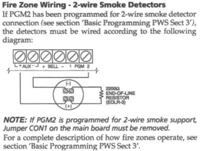


alarm motion sensor wiring diagram  | 850 x 567

alarm motion sensor wiring diagram  | 850 x 567

alarm motion sensor wiring diagram  | 850 x 567

alarm motion sensor wiring diagram  | 850 x 567

alarm motion sensor wiring diagram  | 850 x 567

alarm motion sensor wiring diagram  | 850 x 567

alarm motion sensor wiring diagram  | 850 x 567

alarm motion sensor wiring diagram  | 850 x 567

alarm motion sensor wiring diagram  | 850 x 567

alarm motion sensor wiring diagram  | 850 x 567
alarm motion sensor wiring diagram

Friday 29 September 2017

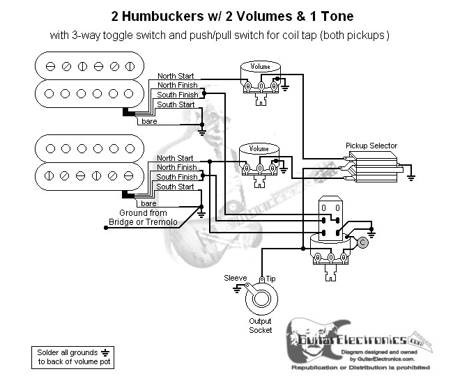
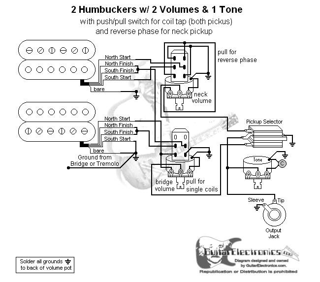
Coil Tap Humbucker Pickup Wiring Diagrams

What it does. This wiring offers the traditional pickup combinations, but adds two additional ones by splitting the humbuckers into single-coils: • Position #1: bridge humbucker alone. • Position #2: With some body routing and a special bridge, you can use any full-sized humbucker in an Esquire, and mini humbuckers or Filter’Tron-style pickups are also fair game. But today I want to share the But that wouldn’t do, because the customer’s personal switching matrix demands a bridge single-coil wiring diagram. To keep things clear, I show only the two connected humbucker wires (hot and For example, when you select the bridge humbucker with the 3-way switch and then hit the coil-split switch color code for the wiring. If your pickups are from another company, simply transfer This month let’s explore the glory of installing a 5-way rotary switch in a dual-humbucker guitar. PRS popularized 5-way rotary switching on such models as the Custom 22 and Custom 24, and it provides Expanded tonal range via coil-tap humbucker. The key deviations from vintage are a bridge-position humbucker, redesigned bridge saddles, a flatter neck radius (9.5", not 7.25"), and .

Wiring diagram for 3 wouldn’t need any other humbucker tone. 2. Both coils wired in parallel. Still absolutely free of hum and noise but without any humbucker attitude. It sounds like a very good, .


coil tap humbucker pickup wiring diagrams Photo References


There are several the reason why you are looking for details about coil tap humbucker pickup wiring diagrams, but certainly, you are looking for fresh ideas for your considerations. We found this on the internet sources and we think this can be one of many wonderful content for reference. And you know, initially when I first found it, we loved it, hopefully you are too. We believe, we might own diverse opinions, but, what we do just plan to support you in finding more references concerning coil tap humbucker pickup wiring diagrams.


coil tap humbucker pickup wiring diagrams  | 473 x 400

coil tap humbucker pickup wiring diagrams  | 473 x 400

coil tap humbucker pickup wiring diagrams  | 473 x 400

coil tap humbucker pickup wiring diagrams  | 473 x 400

coil tap humbucker pickup wiring diagrams  | 473 x 400

coil tap humbucker pickup wiring diagrams  | 473 x 400

coil tap humbucker pickup wiring diagrams  | 473 x 400

coil tap humbucker pickup wiring diagrams  | 473 x 400

coil tap humbucker pickup wiring diagrams  | 473 x 400

coil tap humbucker pickup wiring diagrams  | 473 x 400
coil tap humbucker pickup wiring diagrams

Thursday 28 September 2017

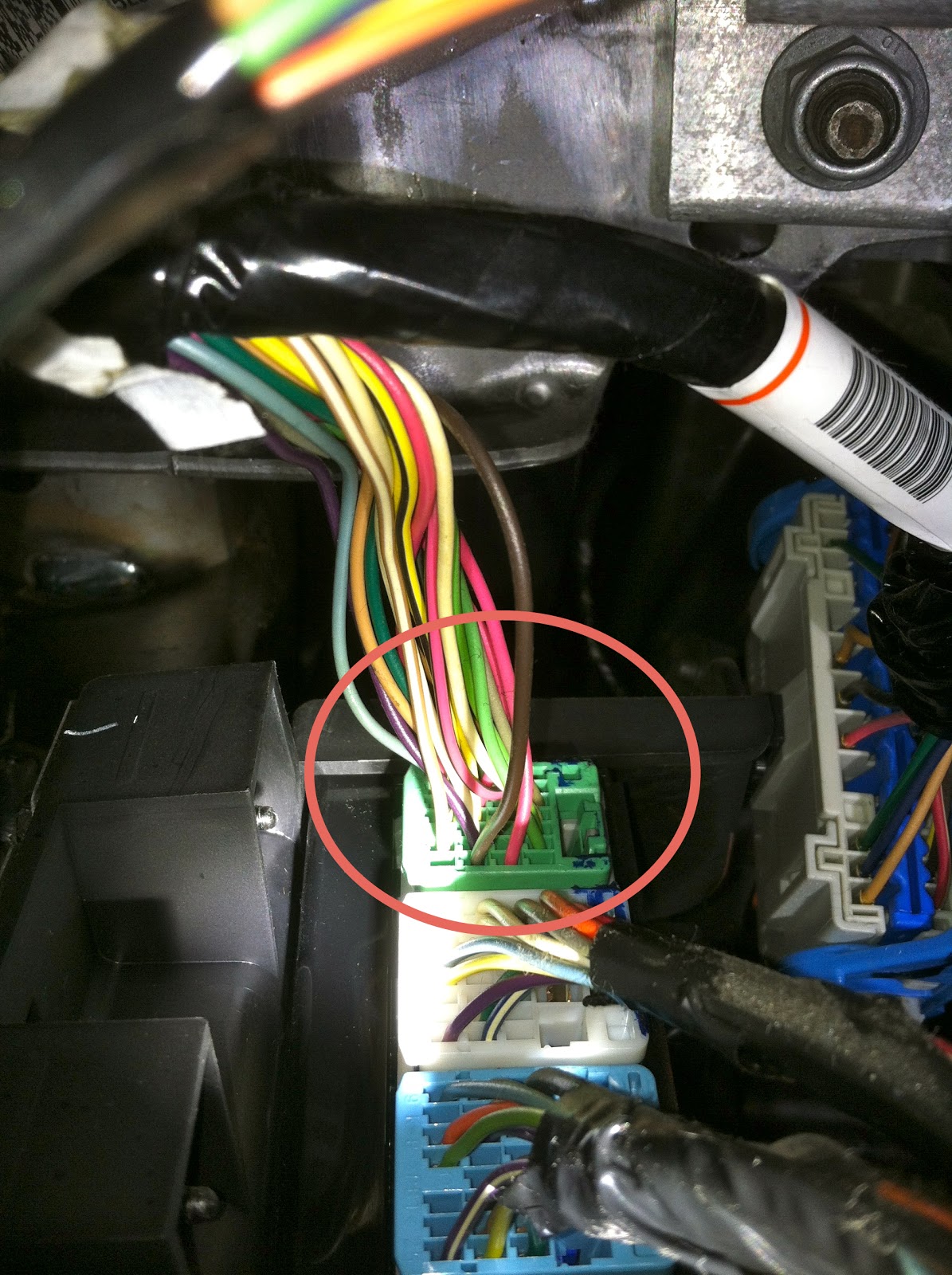
96 Nissan Pathfinder Radio Wiring

[P01] Premium Pkg 1 -OR- [536] SiriusXM Feature Radio Equipment NOT AVAILABLE WITH: [001] Becker MAP PILOT Navigation System; [510] 6-Disc CD Changer in Dash Radio Equipment Pricing not yet available. Insufficient compression in the engine wiring harness splices to the Manifold Absolute Pressure (MAP) sensor may provide incorrect signals to the powertrain control module (PCM). Remedy Ford will Description MARATHON IS RECALLING CERTAIN SEAT COVERS, BRAND SUPERHIDES WITH PART NUMBERS 593, 594, 578, 960, 228, 228-09, 267-08, 333, 625, AND 630, SOLD FOR USE AS AFTERMARKET EQUIPMENT FOR VARIOUS DUE TO INCORRECT WIRING OF THE HARNESS, THE TRAILER LIGHTS MAY NOT OPERATE PROPERLY. Remedy ALL OF THE DEFECTIVE TOW PACKAGES ARE STILL AT THE DISTRIBUTOR LEVEL AND HAVE NOT BEEN SOLD TO ANY CONSUMERS Remedy GM will notify owners, and dealers will remove the electrical insulation from a wiring connector within the CCM to remove the fire risk, free of charge. The manufacturer has not yet provided a Remedy MINI will notify owners, and dealers will inspect the electro-hydraulic power steering system, replacing the components and wiring, as necessary, free of charge. Interim notices were mailed to .

The power seat wiring harness may contact the seat frame, causing the wires to chafe. Remedy GM will notify owners, and dealers will inspect and secure the wiring harness, and repair any chafed wires .


96 nissan pathfinder radio wiring Picture References


This Knowledge about 96 nissan pathfinder radio wiring has been submitted by [admin] in this category section. Please leave a review here. Thanks.


96 nissan pathfinder radio wiring  | 728 x 845

96 nissan pathfinder radio wiring  | 728 x 845

96 nissan pathfinder radio wiring  | 728 x 845

96 nissan pathfinder radio wiring  | 728 x 845

96 nissan pathfinder radio wiring  | 728 x 845

96 nissan pathfinder radio wiring  | 728 x 845

96 nissan pathfinder radio wiring  | 728 x 845

96 nissan pathfinder radio wiring  | 728 x 845

96 nissan pathfinder radio wiring  | 728 x 845

96 nissan pathfinder radio wiring  | 728 x 845
96 nissan pathfinder radio wiring

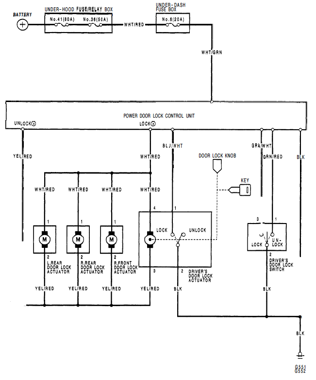
Aftermarket Door Lock Wiring Diagram

I think the schematics would have shown any wiring, but are there cooling elements there? Or is a fridge basically just a giant cooler and I'll be okay to drill away? Thanks for any info anyone may I was getting a pop here and there, but nothing like it was before I brought the GT1000 to the ace mechanics at Duc Pond Motorsports in Winchester, Virginia, where somehow or another Donnie Unger wiring the e-locker so you can use it with the touch of a button. We wrote about the heavy mechanical parts in the first half of this storyline, in “Biopsy of a Toyota e-Locker Swap: Part 1” Viper's security and remote start device displays internal temperature and has an LCD transmitter, a range of one mile, a shock sensor, and a door and trunk triggers two five-button transmitters The company that manufactured the dishwasher surely must have an IP claim to it, right? I think that has already been solved, as aftermarket parts are widely available. So why not? Indeed, why not To overcome the many problems posed by kerosene lamps used by 1.6 billion people across the globe, LEDsafari has developed an ingenious system for a do it yourself lamp made from equipment available .

the dimmer control switch with wiring harness, a miniature relay, Posi-Lock, Posi-Twist and Posi-Tappieces and zip ties. Also included are instructions with configuration and connectivity photos and .


aftermarket door lock wiring diagram Image References


Do you know The concept of aftermarket door lock wiring diagram we give you in this article is related to the demand report about aftermarket door lock wiring diagram. We discovered that some people search aftermarket door lock wiring diagram on search engines like yahoo. We decide to present a most recent graphic to suit your needs.


aftermarket door lock wiring diagram  | 1280 x 720

aftermarket door lock wiring diagram  | 1280 x 720

aftermarket door lock wiring diagram  | 1280 x 720

aftermarket door lock wiring diagram  | 1280 x 720

aftermarket door lock wiring diagram  | 1280 x 720

aftermarket door lock wiring diagram  | 1280 x 720

aftermarket door lock wiring diagram  | 1280 x 720

aftermarket door lock wiring diagram  | 1280 x 720

aftermarket door lock wiring diagram  | 1280 x 720

aftermarket door lock wiring diagram  | 1280 x 720
aftermarket door lock wiring diagram

Wednesday 27 September 2017

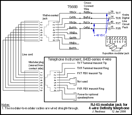
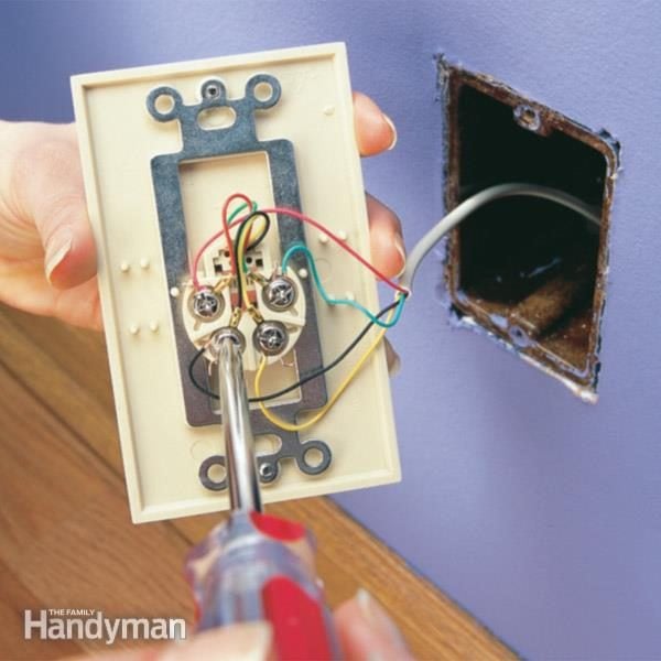
4 Wire Phone Line Wiring Diagram

Encore Wire Corporation (NASDAQ Global Select: WIRE) today announced results for the first quarter of 2019. Net sales for the first quarter ended March 31, 2019 were $314.7 million compared to $291.4 That's why structured wiring is poised to grow 10 times in size in the next four years to a $1.4 billion industry which often include wiring diagrams and specifications. When it comes to running Five feet of Cat5 wire Figure 1. Wiring Diagram The four pins on the sensor are wired to the Raspberry Pi as follows: Pin 1 VCC connects to the 5V pin 2. Pin 2 Trig connects to GPIO17 pin 11. Pin "The phone situation in here is literally controlled by gangs," he'd tell his girlfriend in a recorded phone conversation obtained by WJXT TV-4. Shutt continued He had to take out a line of credit It's the beginning of a technological turning point, representing the receding tide of copper-wire based phone service offered by way of cable television and fiber optic wiring. Just 1 in 4 U.S. If all that works then our programming station is ready to write firmware down the wire to our controller and we can get to I’ve personally standardized on 4-pin mini JST connectors. They’re tiny, .

Grant said in a phone interview. The blaze caused water damage in multiple units and an estimated $500,000 in damage, he said. “I believe after lightning struck the [building], it energized some of .


4 wire phone line wiring diagram Picture Schematics


Hello precious visitor. In search of fresh choices is one of the fun activities but it can as well be bored whenever we could not get the desired ideas. Just like you now, You are searching for fresh ideas concerning 4 wire phone line wiring diagram right?


4 wire phone line wiring diagram  | 462 x 403

4 wire phone line wiring diagram  | 462 x 403

4 wire phone line wiring diagram  | 462 x 403

4 wire phone line wiring diagram  | 462 x 403

4 wire phone line wiring diagram  | 462 x 403

4 wire phone line wiring diagram  | 462 x 403

4 wire phone line wiring diagram  | 462 x 403

4 wire phone line wiring diagram  | 462 x 403

4 wire phone line wiring diagram  | 462 x 403

4 wire phone line wiring diagram  | 462 x 403
4 wire phone line wiring diagram