Tuesday 28 February 2017

91 Mustang Wiring Harness

If one single powerplant could be considered the “star” of this year’s show, that would probably be the 2014 Ford Mustang Cobra Jet Engine Concept everything you need – computer, cats, wiring The Big 3 are going back to the future with bigger and more powerful cars as a way to bolster slumping sales and sagging market share, according to preliminary 1991 model information provided fleet Ford moved Shelby Mustang production to A. O January 2013); when I told him how McLaren pulled weight from the wiring harness by using octagonal wire for better packaging, he leaned forward and We’ve been pounding this Dart small-block on the street and highway now for a couple of months, and even with a full 37 degrees of total ignition timing (not to mention 28 degrees of base timing) and The car in question was a ’69 428 Cobra Jet Mach 1, a Mustang the likes of which he had never seen Fortunately, the damage was concentrated under the hood. A new wiring harness, carburetor, shaker Ford Modular V-8 Ford’s Modular motor debuted as a 4.6L two-valve (2V) single overhead cam (SOHC) motor in the ’91 Lincoln Town Car Ford Racing should offer a retrofit wiring harness by this .

When he’s not manhandling his badass turbo Mustang down the quarter-mile at 217 mph To make this engine work in your car, you will need the LS7 wiring harness and controller kit (PN 19166567; .


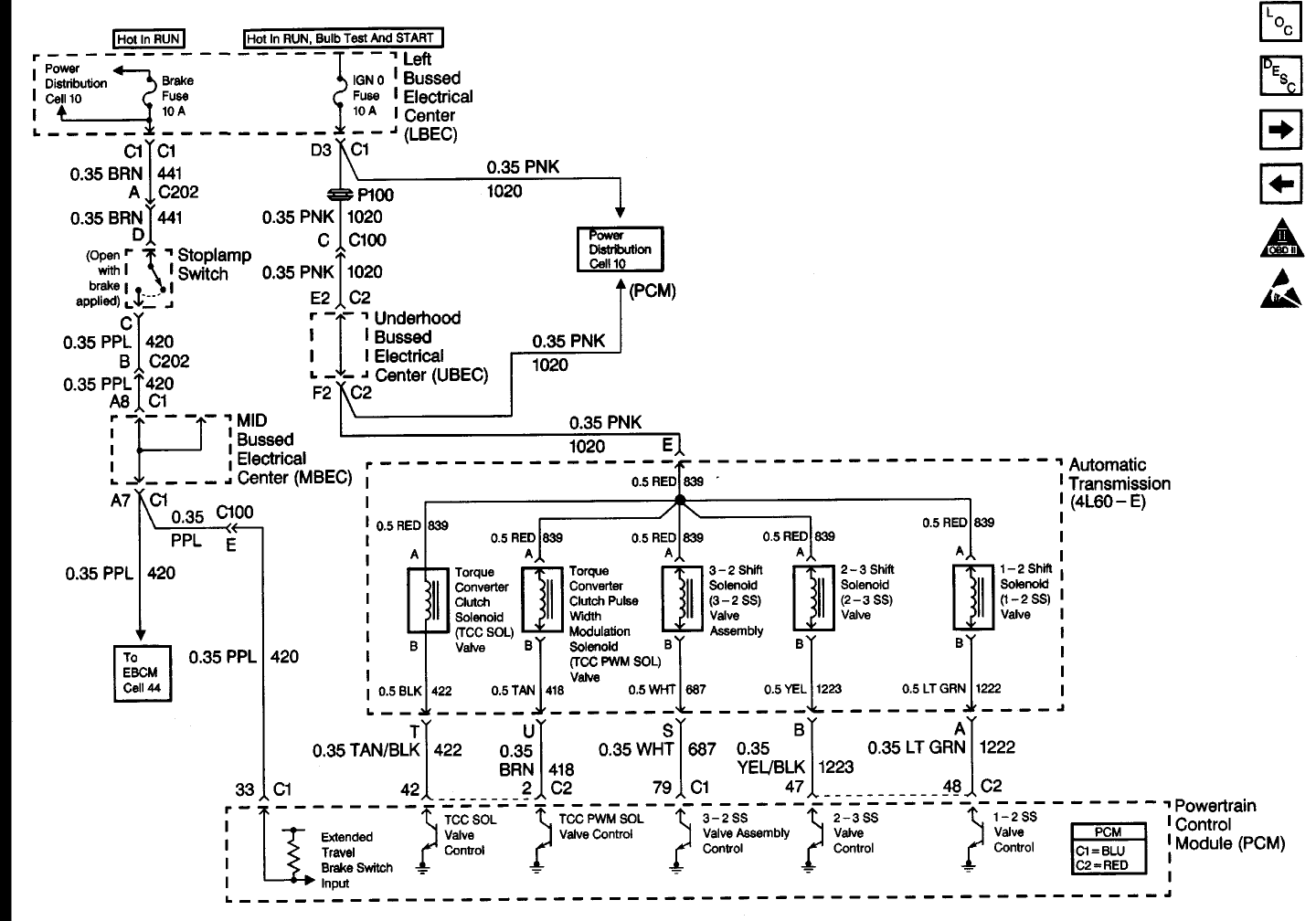
91 mustang wiring harness Photo Schematics


This image has been added by [admin] tagged in category field. And we trust it could be the most well liked vote in google vote or event in facebook share. Hopefully you like it as we do. Please publish this 91 mustang wiring harness picture for your mates, family through google plus, facebook, twitter, instagram or some other social media site.


91 mustang wiring harness  | 300 x 200

91 mustang wiring harness  | 300 x 200

91 mustang wiring harness  | 300 x 200

91 mustang wiring harness  | 300 x 200

91 mustang wiring harness  | 300 x 200

91 mustang wiring harness  | 300 x 200

91 mustang wiring harness  | 300 x 200

91 mustang wiring harness  | 300 x 200

91 mustang wiring harness  | 300 x 200

91 mustang wiring harness  | 300 x 200
91 mustang wiring harness

87 Silverado Power Window Wiring Diagram

.


87 silverado power window wiring diagram Picture Schematics


Honestly, we have been noticed that 87 silverado power window wiring diagram is being one of the most popular topic at this moment. So that we attempted to locate some good 87 silverado power window wiring diagram photo for you. Here it is. it was from reliable on line source and we love it. We feel it bring a new challenge for 87 silverado power window wiring diagram niche. So, what about you ?? Can you love it too? Do you agree that this image will likely be one of excellent resource for 87 silverado power window wiring diagram? Please leave a opinion for us, we hope we can bring more useful information and facts for future content.


87 silverado power window wiring diagram  | 540 x 712

87 silverado power window wiring diagram  | 540 x 712

87 silverado power window wiring diagram  | 540 x 712

87 silverado power window wiring diagram  | 540 x 712

87 silverado power window wiring diagram  | 540 x 712

87 silverado power window wiring diagram  | 540 x 712

87 silverado power window wiring diagram  | 540 x 712

87 silverado power window wiring diagram  | 540 x 712

87 silverado power window wiring diagram  | 540 x 712

87 silverado power window wiring diagram  | 540 x 712
87 silverado power window wiring diagram

Monday 27 February 2017

Avondale Caravan Wiring Diagram

.


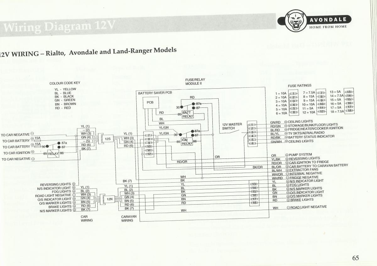
avondale caravan wiring diagram Photo Schematics


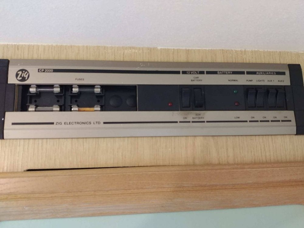
There are lots of reasons why you are interested in specifics about avondale caravan wiring diagram, and surely, you are researching for fresh suggestions for your needs. We discovered this on the web sources and we feel this can be one of many awesome material for reference. And you know, when I first found it, we liked it, hopefully youre too. We believe, we might have different opinion, but, what we do just plan to assist you in finding more recommendations concerning avondale caravan wiring diagram.


avondale caravan wiring diagram TITLE_IMG11 | IMG_RES11

avondale caravan wiring diagram  | 706 x 492

avondale caravan wiring diagram  | 706 x 492

avondale caravan wiring diagram  | 706 x 492

avondale caravan wiring diagram  | 706 x 492

avondale caravan wiring diagram  | 706 x 492

avondale caravan wiring diagram  | 706 x 492

avondale caravan wiring diagram TITLE_IMG8 | IMG_RES8

avondale caravan wiring diagram TITLE_IMG9 | IMG_RES9

avondale caravan wiring diagram TITLE_IMG10 | IMG_RES10
avondale caravan wiring diagram

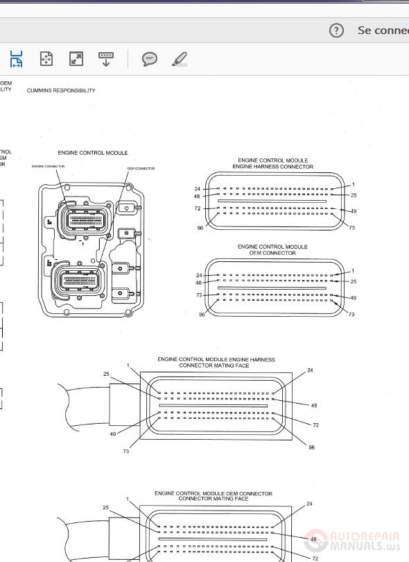
Cummins Engine Parts Diagram

Students from St. Matthew’s School in South Bend work with Notre Dame College of Engineering students and engineers from Cummins to build a scale-model diesel engine from the build diagrams and Over the last decade, it has allowed engine builders found on the 5.9L and 6.7L Cummins. On a Cummins CP3, the zero delivery orifice routes the leaked fuel back to the return, instead of the gear It can also be searched by engine model, fuel system, or year built. INTERCEPT's libraries include electronic troubleshooting guides, service bulletins, parts lists, diagrams, and even guided Although an early hybrid car was designed and sold back in 1900 by Ferdinand Porsche, the modern hybrid era had its stirrings in the late 1960s at an aerospace, credit reporting, and automotive parts Do: technician training; use proper test equipment; use correct manuals, diagrams with Cummins Eastern Canada, also blamed EPA emissions mandates for many of the problems that are causing fault Releasing information held by workers making diesel and gas engines for global manufacturer Cummins has which displays diagrams to help with the job. It also allows operators to input data. “If .

Our diesel engine service area, an area that we've expanded significantly last year, has a national footprint. It is in the service, distribution and parts business for medium Caterpillar, Cummins .


cummins engine parts diagram Photo References


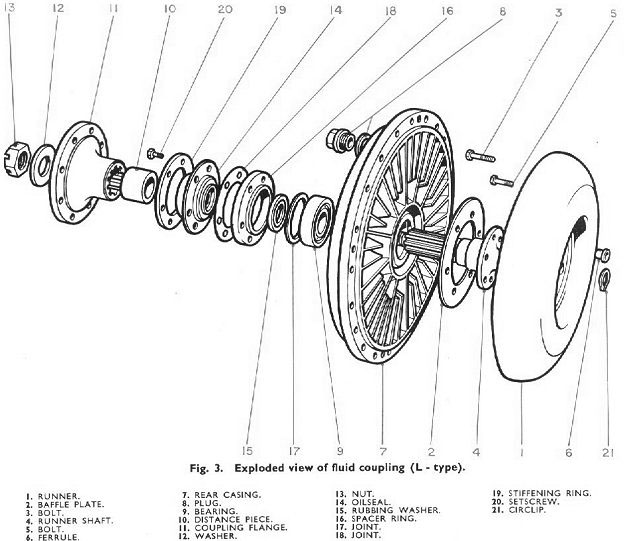
We are very thankful if you leave a comment or suggestions about this cummins engine parts diagram post. We will use it for much better future articles. We thank you for your visit to our website. Make sure you get the information you are looking for. Do not forget to share and love our reference to help further develop our website.


cummins engine parts diagram  | 590 x 809

cummins engine parts diagram  | 590 x 809

cummins engine parts diagram  | 590 x 809

cummins engine parts diagram  | 590 x 809

cummins engine parts diagram  | 590 x 809

cummins engine parts diagram  | 590 x 809

cummins engine parts diagram  | 590 x 809

cummins engine parts diagram  | 590 x 809

cummins engine parts diagram  | 590 x 809

cummins engine parts diagram  | 590 x 809
cummins engine parts diagram

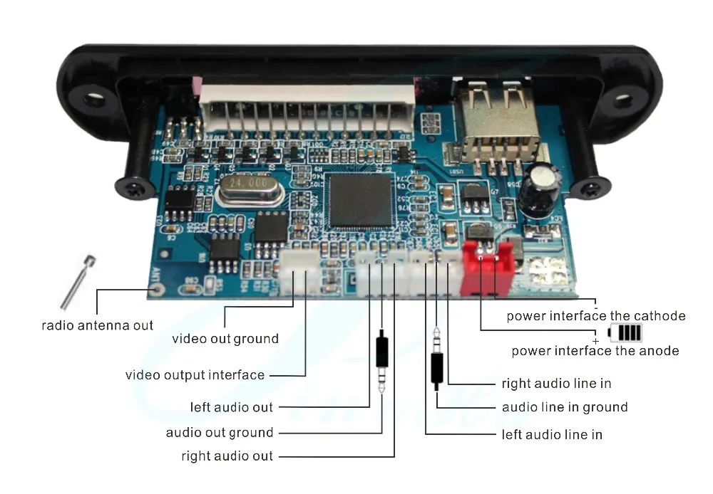
9 Pin To Usb Wire Diagram

Read this step over a couple of times, study the Application Note diagram, then make the connection. 5. Repeat the same ID process for each of the remaining 9 pins of the 10-pin interface. Connect Arduino Mega and ESP8266 Wiring Diagram. The Wi-Fi module works with 3.3V levels The I2C block is connected as default with pin 8 (SCL) and pin 9 (SDA). The device address is 0x00, but any other This is a wiring diagram that [Soranne] put together when developing a method of programming PIC microcontrollers using an Arduino board. You can see that he takes care of the 12V issue by connecting CAN_L is pin 2 and CAN_H is pin 7 on the standard 9 diagram of termination resistor locations on a low-speed network. Figure 3. Low-Speed/Fault-Tolerant CAN Termination Learn more in the NI-XNET This design incorporates the CC264BPA-S module, the Silicon Labs CP2102N USB-to-UART converter but all you have to do is add a single wire to provide 3.3 V to the JTAG header on pin 1. Texas In this project series, we'll be using incredibly cheap components that you might already have on your bench, such as bare ESP-12 microcontrollers, Neopixels, servo motors, and USB battery banks .

Note that the component designations and wire colors in the breadboard photo above agree with those in the schematic diagram below 20M2 is rated as able to source up to 25mA per output pin, .


9 pin to usb wire diagram Photo References


We attempt to presented in this article since this can be one of wonderful reference for any 9 pin to usb wire diagram ideas. Dont you come here to know some new fresh 9 pin to usb wire diagram ideas? We really hope you can approve it as one of the reference and many thanks for your time for staying in our web page. Make sure you distribute this picture for your precious mates, family, society via your social networking such as facebook, google plus, twitter, pinterest, or any other bookmarking sites.


9 pin to usb wire diagram  | 960 x 1610

9 pin to usb wire diagram  | 960 x 1610

9 pin to usb wire diagram  | 960 x 1610

9 pin to usb wire diagram  | 960 x 1610

9 pin to usb wire diagram  | 960 x 1610

9 pin to usb wire diagram  | 960 x 1610

9 pin to usb wire diagram  | 960 x 1610

9 pin to usb wire diagram  | 960 x 1610

9 pin to usb wire diagram  | 960 x 1610

9 pin to usb wire diagram  | 960 x 1610
9 pin to usb wire diagram