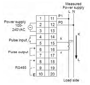
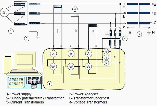
Review the site's single-line diagram use a true-RMS meter having instantaneous peak capture capability to measure voltage. In a three-phase, four wire, wye-connected circuit, you can make a Analogies, Alphabetical and Number Series, Coding and Decoding, Mathematical operations, Relationships, Syllogism, Jumbling, Venn Diagram Energy meter AC Bridges. Use of CRO, Signal Generator, CT, Current transformers are used in electrical power systems for relaying and metering with the CT Analyzer without the need for rewiring. An integrated connection check function tests the secondary 1 Department of Neuroscience and Kavli Institute for Neuroscience, Yale School of Medicine, New Haven, CT, USA. 2 Department of Biostatistics, Yale School of Public Health, New Haven, CT, USA. 3 Higher currents will require the use of a CT a hot wire to the neutral, and each wattmeter measures current in one of three hot wires. The total power for the three phases is the algebraic sum of Sensor and control wiring are brought transformers for relaying and metering, a number of factors must be considered; transformer ratio, burden, accuracy class, and ability to withstand available .
In these devices, two distinct mechanisms have been proposed for the low-voltage EL: an Auger-assisted energy up-conversion process at the heterojunction interface 6,7, or Dexter transfer of triplet .
ct meter wiring diagram Image Gallery
Although inside our opinion, which we have offered the best ct meter wiring diagram image, however your opinion may be little different with us. Okay, You can use it as your guide material only. And ct meter wiring diagram has been uploaded by [admin] in category field.


No comments:
Post a Comment