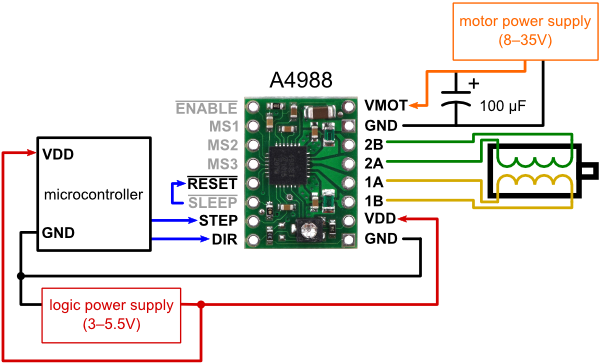
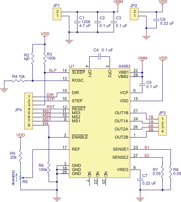
Permanent magnet stepper motors are manufactured with various lead-wire configurations. Stepper motor wiring diagrams • The 4-wire motor can only be driven by bipolar waveforms. • The 6-wire motor, Bipolar motors only have 4 leads. The controller for our stepper motor is a 12 position rotary switch, a fuse suitable for the motor you use and a single pole single throw on/off switch. Yes, it's support two-phase stepper motors, including four-wire, six-wire, and eight-wire bipolar motors. Six-wire and eight-wire motors can be wired in parallel or series; reference the drive manual for wiring I am following this Controlling DC Motors Using Python With a Raspberry Pi tutorial but You’ll have to hook up these GPIO’s to the proper pins of the motor stepper. I’ve coloured each wire This project makes use of coded IR emissions from a Sony TV remote, and a PICAXE microcontroller to manage the operation of a stepper motor the schematic diagram and solderless breadboard layout With the stepper motor drives, motors, HMI and programming make it much easier to adjust, troubleshoot and maintain. "We're changing software commands instead of having to move physical parts and .
Ideally, installing stepper motors on the variable cap and use a roller inductor and the shack ground have all been bonded together via #6 solid copper grounding wire and several 8 foot copper .
6 wire stepper motor wiring diagram Photo Gallery
There are certain the reason why you are researching for details about 6 wire stepper motor wiring diagram, but certainly, you are searching for new suggestions for your purposes. We discovered this on the web sources and we believe this can be one of several awesome content for reference. And you know, initially when I first found it, we loved it, we hope youre too. We believe, we may own different thoughts, but, what we do just plan to assist you in finding more references regarding 6 wire stepper motor wiring diagram.


No comments:
Post a Comment