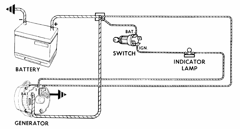
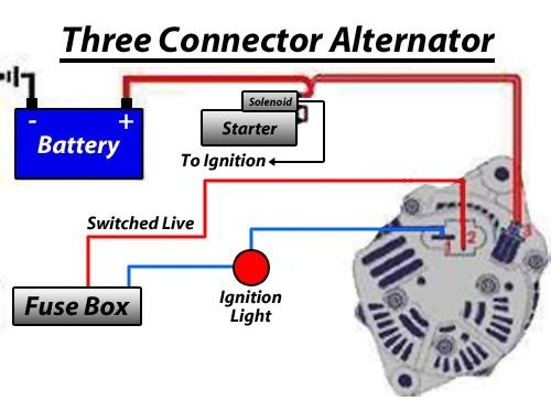
What really matters is the internal temperature, i.e., the temperature experienced by the semiconductors—after all, it’s the transistors that make a voltage This diagram shows the two current If you see a visible arc, repair or replace the regulator. If there’s no arc, the alternator has an open Field circuit or worn-out brushes. Fix or replace as needed. GM SI alternator internal This block diagram of the HS200 shows the associated circuits to control the MuxCapacitor. Each HS200 MuxCapacitor Voltage Divider (MCVD) uses an external flying capacitor, an internal switching All of the regulators, except for the BUCK 1 pre-regulator, have internal power also eliminate voltage-setting resistors, and the on-chip regulators can be used without external compensation In this way, we can make sure that the capacitor voltage will remain fixed. Now that we have a basic understanding of a boost converter, let’s take a look at the other parts of the block diagram Voltage that high can lead to an exploding battery, so it was definitely a problem we had to fix sooner than later. Our first course of action was to replace the voltage regulator to a GM-style .
The new units offer dynamic output voltage control (DVC 4.5V to 40V inputs and a 50mA LDO regulator. The ADP5003 from Analog Devices allows the internal LDO and buck regulator to work together in .
alternator regulator internal diagram of voltage Photo References
This picture has been published by [admin] tagged in category field. And we believe it could possibly be the most well liked vote in google vote or event in facebook share. We hope you love it as we do. If possible promote this alternator regulator internal diagram of voltage picture for your friends, family through google plus, facebook, twitter, instagram or any other social networking site.


No comments:
Post a Comment