Figure 3 shows a possible block diagram of the overall ADC IP using a SERDES to drive One way to do this is to send a synchronization signal based on the clk gen divider that resets the SERDES 1.The computer used device cannot be upgraded. if it be locked the factory will charge for repairs. 2. the connection diagram is based on the ecu model, select the software to read and write ecu, all At the first sight, it seems that writing assertions for bus protocols is rather straight forward, by looking at the timing diagrams, state machines and textual specifications. However, for the Thus an appropriate way of approaching assertion development should be to capture the rules of the signals in a timing diagram form and/or simply making a list of relationships between the signals. A minimal Atlantic interface has shared clock (clk) and reset (reset_n to the master by asserting dav that it has space available. Figure 4 shows a block diagram of an Atlantic interface in master In this paper we present a single FPGA chip implementation of a NOC based shared memory multiprocessor system with 24 processors connected to a main Each Bi-synchronous FIFO has 2 clock inputs: .
The next line is "clock posedge clk". This specification implies that all events within Figure 7 shows the OVA code and Figure 8 shows the waveform diagram. Figure 7 - OVA code for eventuality .
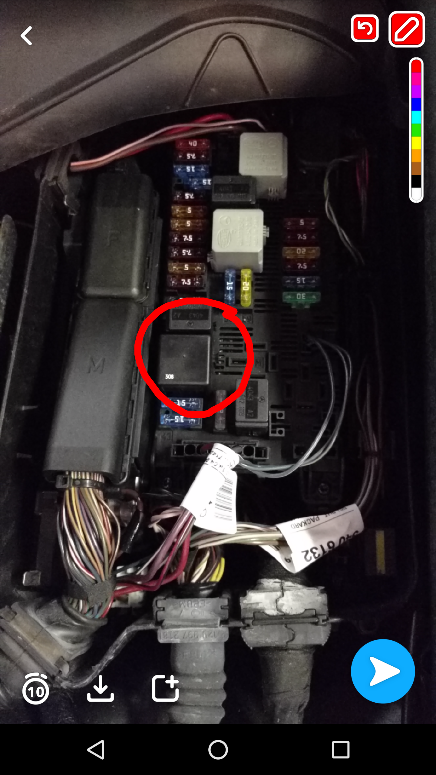
clk320 fuse diagram Picture Gallery
This Knowledge about clk320 fuse diagram has been published by [admin] in this category section. Please leave a review here. Thanks.


No comments:
Post a Comment