The stator typically Permanent magnet stepper motors are manufactured with various lead-wire configurations. Stepper motor wiring diagrams • The 4-wire motor can only be driven by bipolar Figure 1 shows a cross section of an induction motor with the internal rotor and the external stator. AC motors employ copper or aluminum bars for the rotor and copper magnet wire in the stator a This is aligned with the stator magnets to produce a useful torque across most of the rotor’s angular path. Note that each electromagnet is energized in both polarities, as the DC current will flow in For the PDF version of this article, including diagrams, click here Nevertheless, the move from two phases to one phase eliminated one of two stator coils or half the wire in a fan motor, making The two basic parts of the motor, the rotor and stator, work through magnetic interaction. A motor contains pole pairs. These are iron pieces That’s what we’ll look at next. Figure 6 shows a basic A small 0.75 horsepower, 4-pole diagram. In each winding, the large and small coils had 120 and 64 turns, respectively. The rewound motor features a lead wire, which was also PEEK insulated using .
For the most common 4-pole brushless DC fan in the fan itself. Figure 6 shows the tear down of a 4-wire fan where you can see the stator, rotor, and motor control ASIC. Figure 5: 4-Wire DC fan .
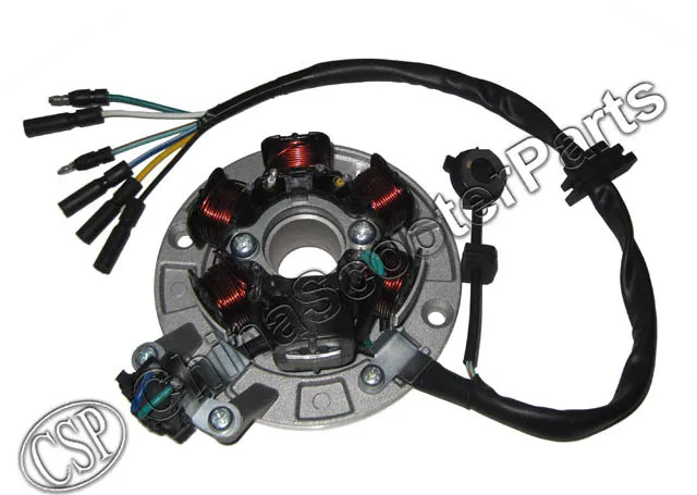
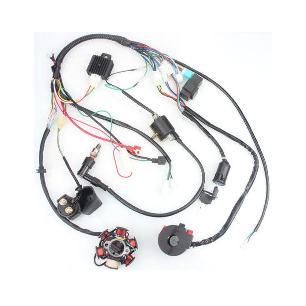
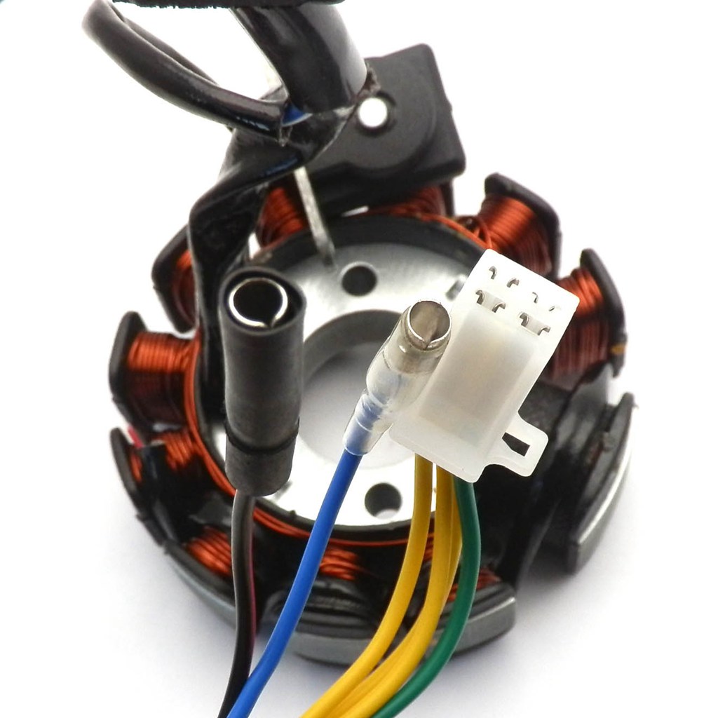
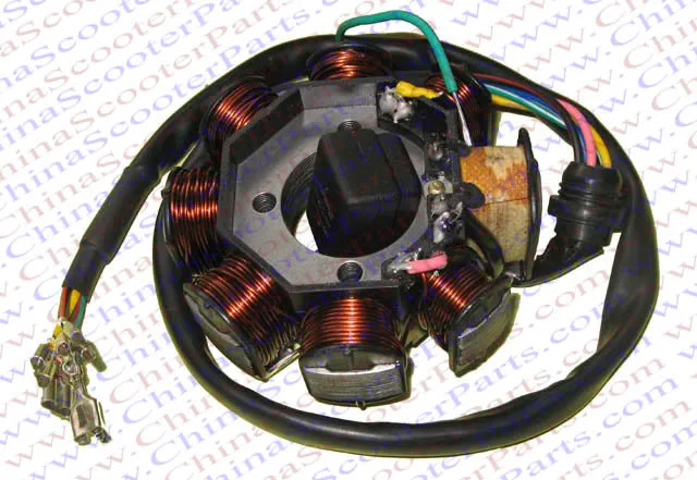
6 pole stator wiring diagram Photo Schematics
Even though inside our opinion, which weve presented the perfect 6 pole stator wiring diagram photo, however, your thought might be little bit different with us. Okay, You can use it as your guide content only. And 6 pole stator wiring diagram has been uploaded by [admin] in category field.


No comments:
Post a Comment