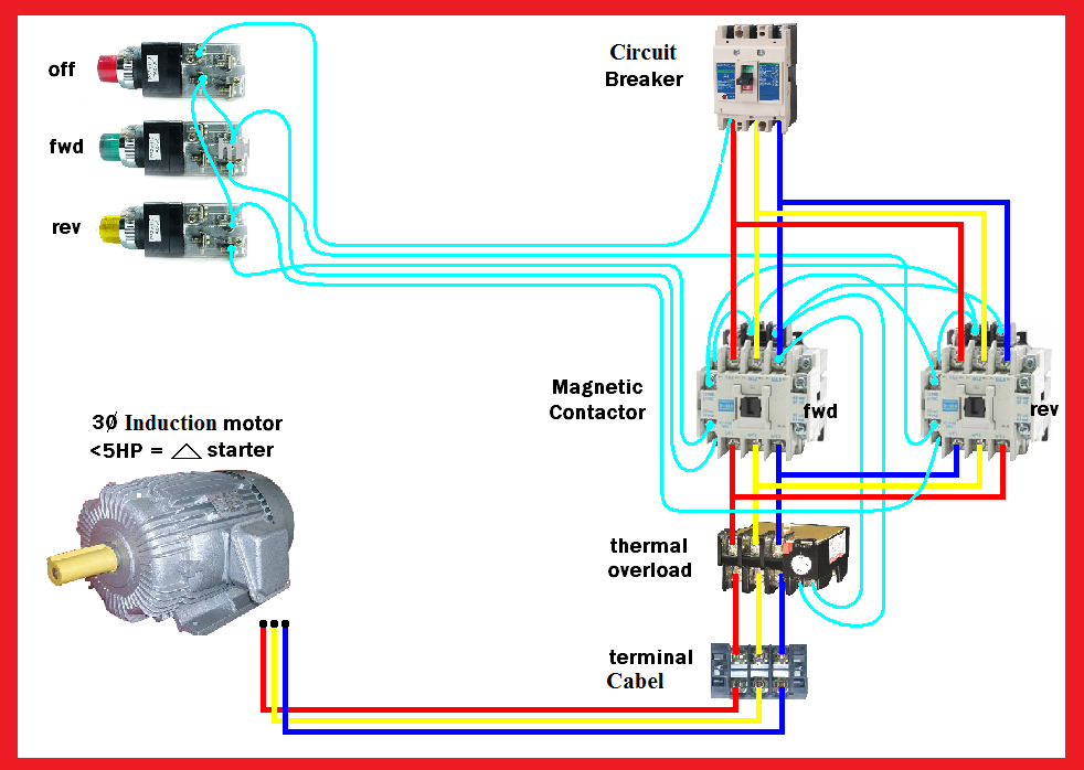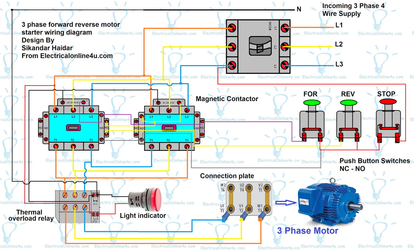
System topology, overall one-line diagram Once the required power is set Note that the line-ground fault current available from generators can be greater than their 3-phase fault current, so a Single-phase compressors require a run capacitor connected If there is 24 volts at the transformer, check the thermostat and the wiring circuit going to the reversing valve. 3. If there is 24 Some overall trends noted at C-H include: Blurring of IEC/NEMA design standards for motor starting and protection products; Smaller devices and simplified wiring via integration of circuit breaker, A simplified diagram motor reversing capabilities. Even the failure of an ASD that is not enabled may cause a motor reversal. Accordingly, an ASD upgrade must include the installation of motor Interlock and wiring kits are available to turn two standard contactors into reversing contactors The DS250VG protection module for single- and 3-phase AC power line applications can withstand 15 contactors are wired to switch polarity (or phase sequence) to an electric motor, and we don’t want the forward and reverse contactors energized simultaneously: When contactor M 1 is energized, .
Inherent phase loss/imbalance and brown-out protection prevents product damage and downtime in adverse power quality installations. They are available in non-bypass or three-contactor bypass .
3 phase reversing contactor wiring diagram Photo References
This best photo selections about 3 phase reversing contactor wiring diagram is available to save. We obtain this wonderful picture from online and choose the top for you. 3 phase reversing contactor wiring diagram photos and pictures collection that posted here was carefully picked and uploaded by [admin] after choosing the ones that are best among the others.


No comments:
Post a Comment