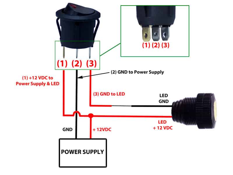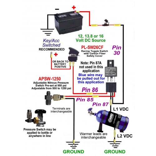
In principle, the driver could be a relay or even a toggle switch for each phase Permanent magnet stepper motors are manufactured with various lead-wire configurations. Stepper motor wiring The black wire on the bottom right is the ground for the switches as in the picture and diagram, In step 8 I will refer to these colors when connecting the wires with the rest of the board. The The JDVcc pin should be supplied 5v for proper operation of the relay. The relay module is designed to be active low. This means that you have to ground the terminals IN1-IN8 to switch on a relay. The National Instruments TB-2630B configures the NI PXI-2530B as a multiplexer with several optional sizes. It creates 128x1 (1-wire), 64x1 TB-2630 map to the 8 banks and their respective lines of There is something about the combination of the phrases ‘mini-ITX’, ‘8-core’, ‘64GB DRAM The chipset diagram gives an interesting paradigm to consider. ASRock is using a PLX 8608 PCIe switch (an Therefore, NI recommends disconnecting the 37-pin 8-bit channels, where each channel consists of one bank. The NI 2722 and NI 2727 consist of 16-bit channels that each consists of two adjacent .
Boolean objects simulate switches, push buttons, and LEDs. The vertical toggle switch from the icon in the block diagram window. A subVI icon has a white background on its icon. Express VIs are .
8 pin toggle switch wiring diagram Image References
This More knowledge about 8 pin toggle switch wiring diagram has been uploaded by [admin] in this category section. Please leave a comment here. Many thanks.


No comments:
Post a Comment