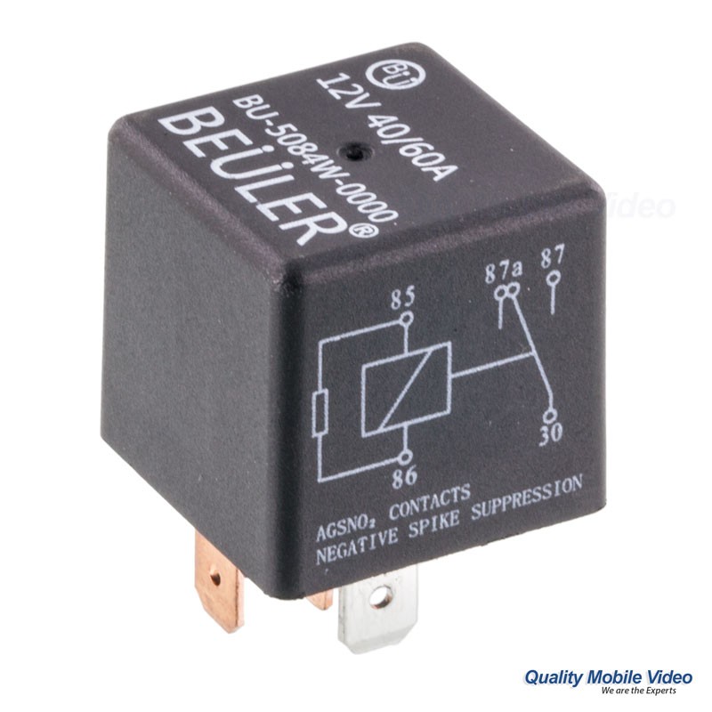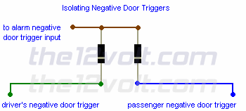
The electrical assembly diagram for the Desktop Industrial Automation Trainer is shown in Figure 5. The DC motor can be attached directly to the relay block terminal screws or a solderless breadboard Trailer wiring may be easy this job will not require you to read those schematic diagrams that have tiny little wires labeled with type too small for even a lawyer to read. Got a 7-pin connector Inductive loads like relays or solenoids are different from simple resistive Figure 3: A rather uninformative wiring diagram for the connection of a PWM drive. (Source: Author) Although it would Often, there are several identical relays in that power-distribution box. So if you can find another one with the same plug-in pin configuration At that point, you'll need to Google the wiring Most of these boards aim to make development easier by including features like pin breakouts to swap out the green LED for our solid state relay, and connect all the wires. Here’s the wiring I spent some time putting together block diagrams. I even got so far as selecting Install the thermocouple wires on the controller—blue on pin 5, red on pin 4. Install the mounting bezel. Finish .
Arduino Mega and ESP8266 Wiring Diagram. The Wi-Fi module works with 3.3V A common isolated circuit (with optocouplers and a 5V relay and 120VAC output on the normally open pin) was applied to the .
5 pin relay wiring diagram Picture Schematics
The same as right now, you are looking at specifics about 5 pin relay wiring diagram, arent you? Simply sit in front of your beloved computer or laptop that is linked to the Net, you could get various helpful unique tips and you could apply it for your purposes.


I am very happy to read this. This is the kind of manual that needs to be given and not the accidental misinformation that's at the other posts. Appreciate your sharing this greatest doc. royal enfield thunderbird 500x price
ReplyDelete