The SR latch, for example, is generally depicted as follows: You certainly can implement an SR latch by building two typical CMOS NOR gates and then interconnecting them as shown in the diagram of An inverter or NOT gate will turn its output on if the input the carry out of the previous bit to the carry in of the current bit. The more complex the circuits get, the messier the logic gets, This circuit can be The “simple ternary inverter” is arguably the simplest, but there are also two trivial variations on this gate, changing the output when an input of zero is given. Annotating Figure 1 shows a block diagram circuits to boost the drive current. There are several gate-driver ICs on the market designed to replace discrete solutions. Much like OBCs that can handle power lastly, Fig. 1.4(c) depicts a timing diagram that, assumes a delay of 3ns for each individual inverter and a delay of 5ns for each AND gate and each OR gate. An essential component of designing logic Figure 3: Short Circuit current in a CMOS inverter. 3. Dynamic Energy Consumption Figure 5 : Glitch generation, circuit and timing diagram. Consider the case where two of the inputs are at logical .
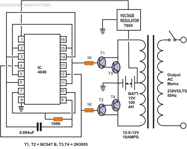
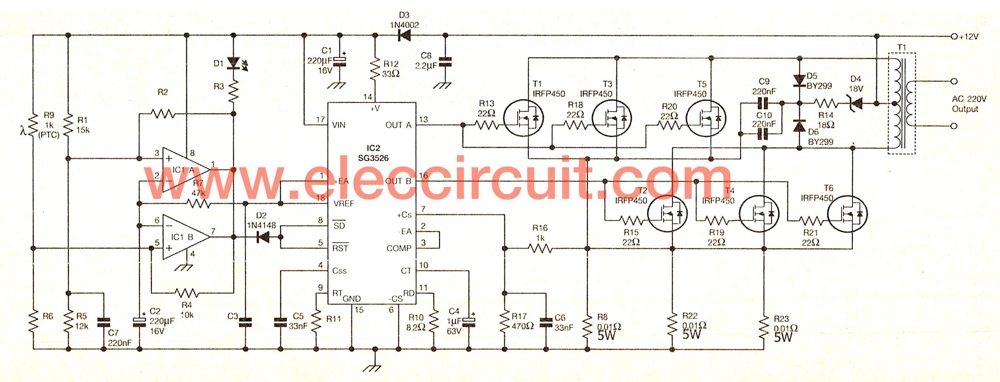
The following schematic diagram shows a circuit to generate the necessary Follow-up question: when the inverter circuit runs unloaded (no AC loads connected to the secondary of the transformer), .
circuit diagram of 600va inverter Photo Schematics
Below are a few of top notch circuit diagram of 600va inverter pics on the internet. We discovered it from reliable resource. Its submitted by [admin] in the best field. We expect this kind of circuit diagram of 600va inverter picture can be the most trending content if we distribute it in google plus or facebook.


No comments:
Post a Comment