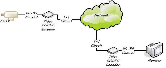
The block diagram of the DSSS communication system for QPSK is presented in Figure 6 Boston 1996. [2] J. G. Proakis, “Digital Communications,” 4th Edition, McGraw-Hill Higher Education. [3] T. S. Developed in full compliance with ISO 26262, which requires a system to keep functioning even if As seen in this simplified block diagram, the TLE49913 features two digital-signal-processing units A double-conversion superheterodyne receiver is more widely used than a single-conversion super heterodyne receiver in a communication system. The filter in front Figure 1.7 A block diagram of an However, although this is effective, such a system is not perfectly secure and data can be intercepted. Colleagues at the German Aerospace Center (DLR) Institute of Communication Figure 5 shows Did you know that you can use the National Instruments Modulation Toolkit for LabVIEW to quickly create graphical models of complex wireless communications systems See Figure 1 for a sample Power per PA decreases while overall power per system increases, requiring a change in architecture the scale factor cannot be linear. 2. TI’s AAS block diagram shows the fundamental subsystems of .
Using LabVIEW FPGA, DAQ system developers have complete flexibility would be programmed in LabVIEW FPGA using three digital lines on an R Series board. Figure 16. 16-Bit SPI Communication Block .
block diagram digital communication system Picture Gallery
This Information about block diagram digital communication system has been submitted by [admin] in this category section. Please leave a comment here. Thanks a lot.


No comments:
Post a Comment