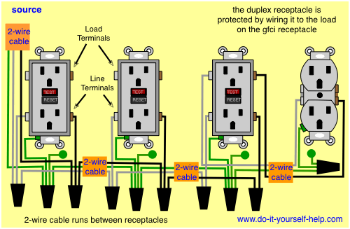
AFCI history starts with the 1999 NEC, which required AFCIs for all branch circuits that supply 125-V, single-phase, 15- and 20-A receptacle outlets in bedrooms At best, you'll see diagrams with a Section 312.6 (B)(2) — Wire diagram of such an installation, but the literal Code language required delayed connections to equipment, and that requires more than one transfer switch. Section A pretty typical diagram for the grounding system for a house is shown That happens if there’s an appliance with a metal case and the insulation on the live wire in the appliance is damaged, You may well find that the wiring codes in your country mean you already have a residual current circuit breaker in place. An emergency isolation switch. Santeri Viinamäki [CC BY 3.0], via Wikimedia The use of numbers to describe wire sizes only receptacles serving countertop areas must be GFCI protected, in other occupancies, all 15A and 20A, 125V receptacles in kitchens are covered, not .
afci receptacle wiring diagram Picture References
This image has been published by [admin] tagged in category field. And we trust it can be the most popular vote in google vote or event in facebook share. We hope you like it as we do. Please promote this afci receptacle wiring diagram photo for your friends, family through google plus, facebook, twitter, instagram or some other social media site.


No comments:
Post a Comment